By Oryan Inbar
Development work continues on the experimental “Time Sense” prototype for cyborg Neil Harbisson. The end goal of the project is to create a permanently-wearable ‘soft device’ that allows Neil to feel the sensation of time passing throughout the day, as a micro-heat sensation around the circumference of his head.
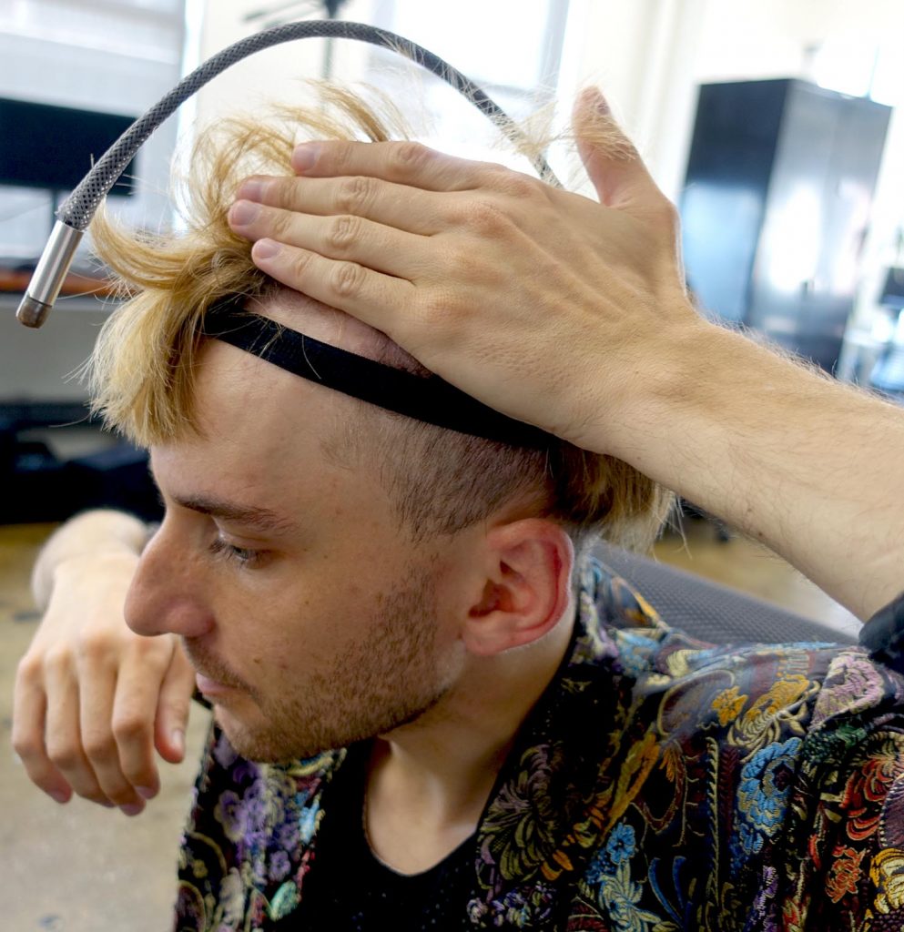
Neil showing where he wants to sense time

This is a project which involves several stages cut across multiple disciplines. In this post, I’m going to talk about the industrial design process I am undertaking, and how it has played out in practice so far on this project.
The Wearable Prototyping Stage
First, a little orientation as to where our current round of industrial design fits into this project. In the development of any cyborg sense, the initial goal is always to create a comfortable wearable with embedded electronics, including sensors or actuators that the cyborgs can actually feel.
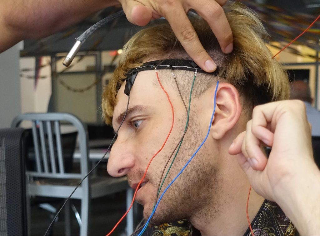
Neil wearing the functional proof of concept
These wearables allow the cyborgs to actually experience a new prototypical sense, so they can learn about what works and what doesn’t before developing it further. Based on that experience, they can decide what direction to go next, including potentially developing implants that will become integrated into the human, merging technology and biology.
The first part of this ‘wearable prototyping’ stage was a functional proof of concept, shown above, which we created during the Cyborg Foundation’s residency at ThoughtWorks in the summer of 2016.
I am now working on the next stage — creating a durable physical wearable, in which to combine new, miniature electronics with a unique industrial design, thereby creating a smoother user experience for the cyborgs.
3D Model and Dummy Wearable
To begin the process of creating the durable wearable, I created a 3D model of the prototype, shown in the picture below. The model incorporates, miniature versions of the electronics from the functional proof of concept, along with materials research conducted by ThoughtWorks employee Caihong Liu, based in Chengdu China, during the residency.
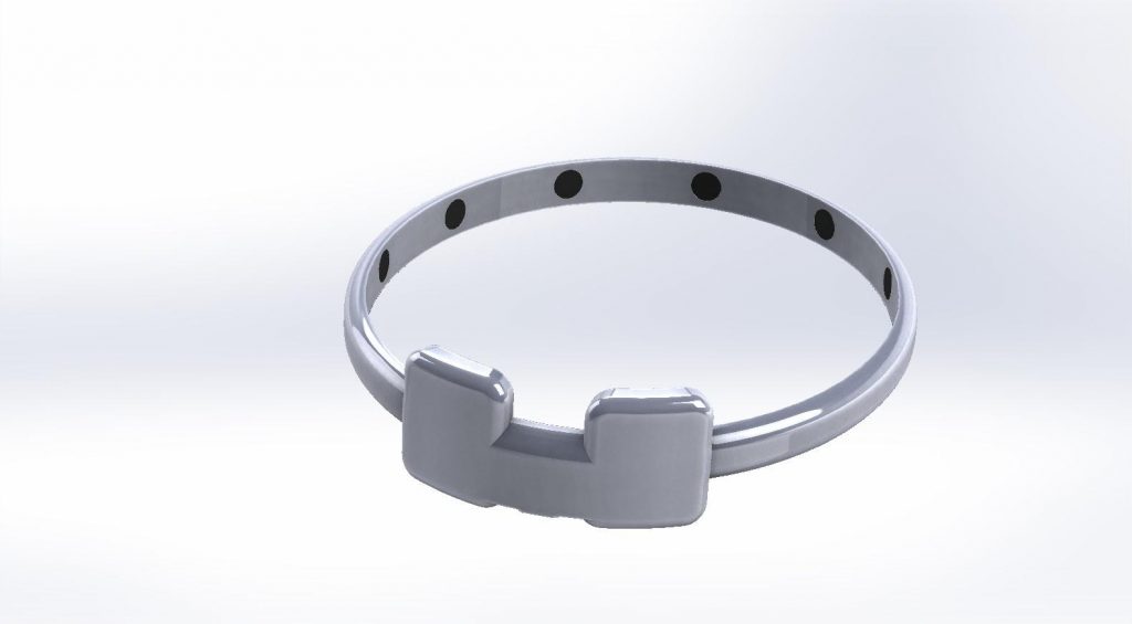
A 3D visualization of the wearable
Next, based on the prototype model, I created in 3D a two-part mold from which the wearable could be cast. The holes in both parts seen in the picture below, are for bolting the parts together (mating) when injecting the silicon into the negative space created in between the two parts. This empty space will contain the electronics when injecting the silicon in the final version.
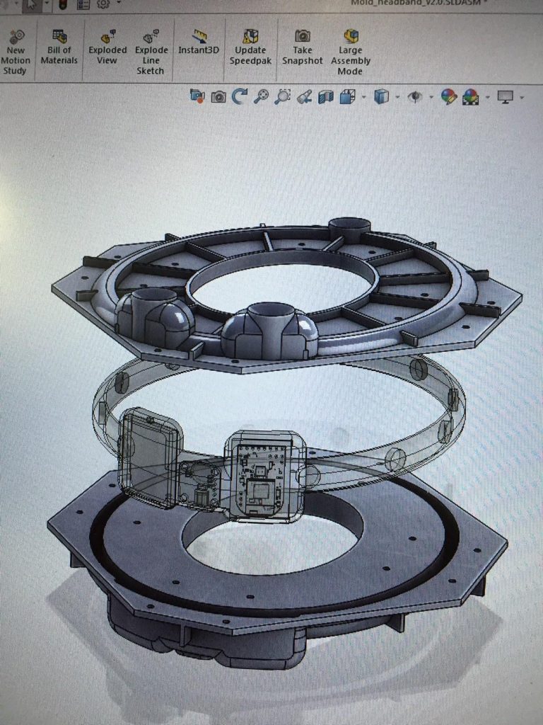
A 3D visualization of the two-part mold creating the wearable
Next, I produced a “dummy” physical wearable based on that 3D model, which does not contain electronics. This version of the wearable gives Neil his first chance to try on and report back so we can make design adjustments before moving towards a final design.
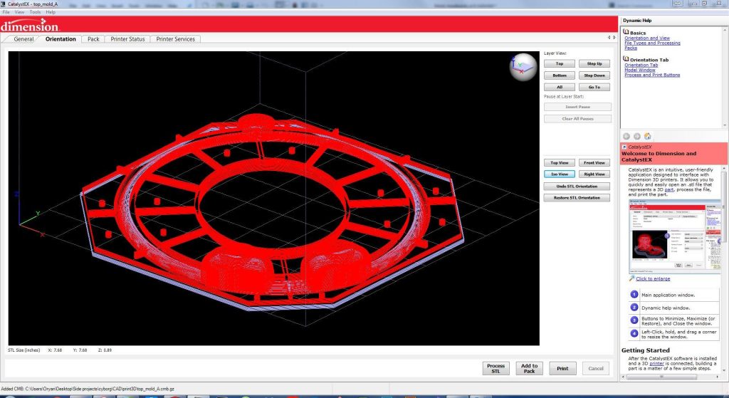
The upper mold model before printing (red = ABS, blue = HIPS)
In this initial test round, Neil is reporting specifically on comfort of the physical headband. This is highly important, because when complete Neil intends to wear the headband 24 hours a day, seven days a week, as part of his process toward considering developing an implant sometime in the future.
Production of the Headband
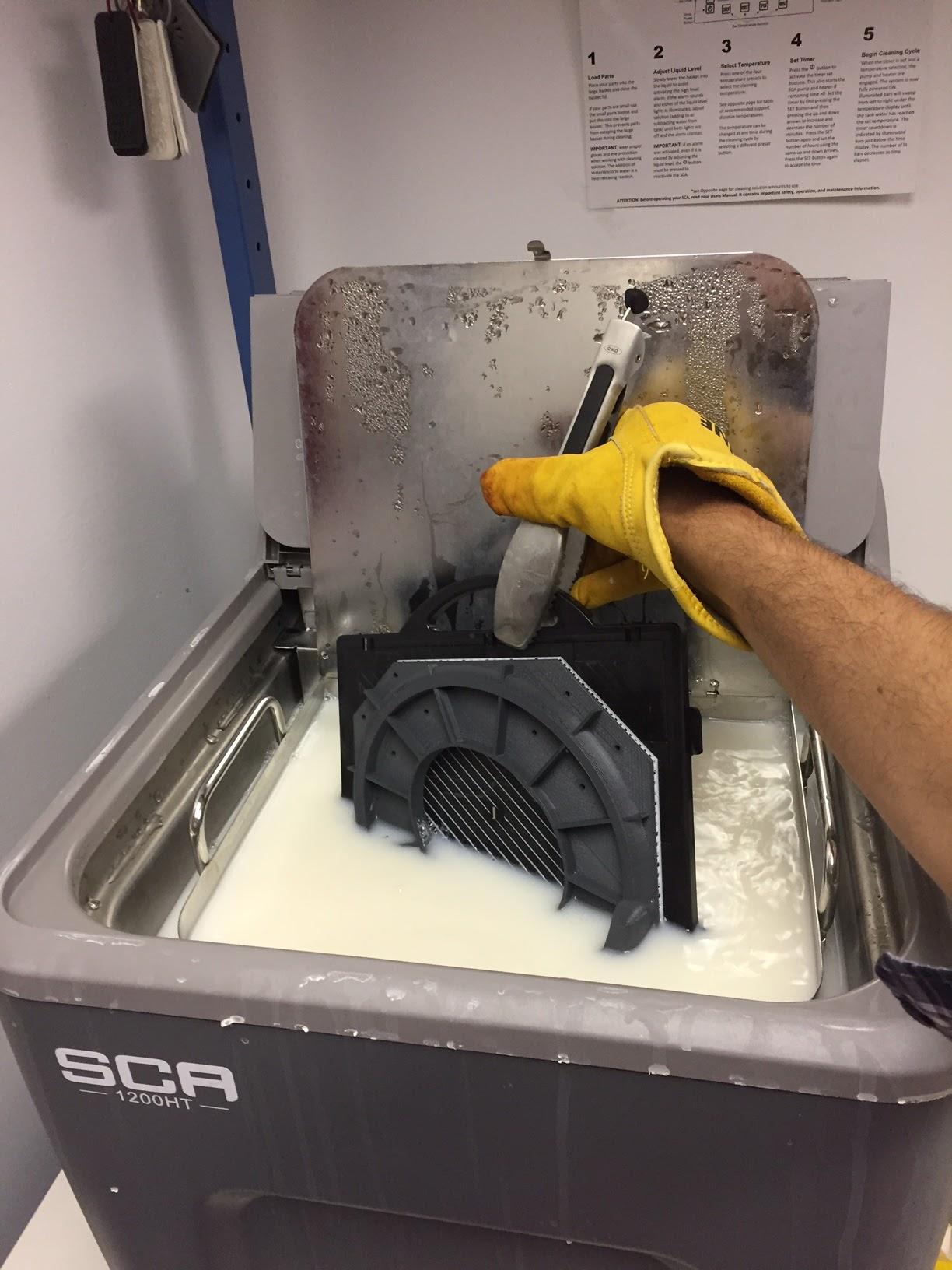
As shown in the image above, the first stage in creating the dummy wearable was to 3D print the two-part mold. The material used in the uPrint 3D printer is ABS (Acrylonitrile-Butadiene-Styrene), in conjunction with HIPS (High Impact Polystyrene). The latter is used as support material which allows creating shapes with overhanging features, and holds elements in place during printing and cooling. The HIPS support material was then removed by submerging the complete final print into a limonene solution, which dissolves HIPS without affecting the ABS in the parts.

Removing the support structures inside the mold
Next, the two molds were sanded to smooth out the surfaces that are meant to be mated – the better the mating is, the less silicon will squeeze out when the two parts are connected, thus creating a better part. A secondary treatment typically uses acetone vapor, which is very caustic on the plastic and if done right can produce high smoothness with little loss of detail. However, that level of aesthetic treatment was beyond the scope of this first iteration and so was skipped.
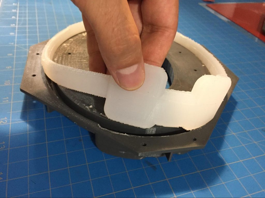
Extracting the wearable from the mold
The silicon material chosen for the actual wearable was then mixed, and the solution placed inside a vacuum chamber to extract any bubbles that may have formed. The silicon was injected into the mold, and the mold and silicon together took another turn in the vacuum chamber to further reduce bubbling.
Once the silicon had set, the mold could be carefully removed, and the wearable extracted ready for testing.
Testing the Fit
Given that this was our first run, I expected that the dummy wearable might be too tight or too loose. However, in testing, Neil reported wearing it for several days without discomfort.
I explained to him that the flexibility of the headband would be somewhat reduced with the introduction of the electrical components inside it.
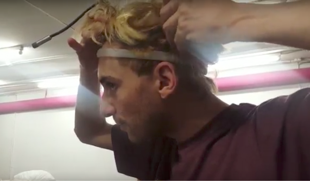
Neil trying the dummy model for the first time
We are now planning to refine the 3D model, print a new version of the headband, and move forward with the electronics. Specifically, we will cast the individual heat elements through which Neil will sense time, and then solder the wires and electrical components from the design and embed them in the new headband.
Acknowledgments:
Mike Brody – Structural and Mechanical
Sam Sadtler – Concept
Andy Mcwilliams – Curating of this post
Ellen Pearlman – Editing
Christina Xenides – Editing